Ovron Motor
Choosing the right Electric Gear Motor is rarely a simple catalog decision. The correct unit must match the machine’s load, speed, duty cycle, space, and operating environment. A motor that looks powerful on paper may overheat under repeated starts, stall during peak loads, or wear quickly when misaligned.
Austin Hughes, author of Electric Motors and Drives, describes the motor as “the heart of any drive system.” That observation remains practical today. The gearbox is equally important because it converts speed into usable torque. Engineers should examine the reduction ratio, rated torque, starting torque, efficiency, backlash, shaft configuration, and expected service life. Small details matter. A dusty workshop, cold storage room, or washdown area can change the specification completely.
This guide, “10 Tips for Choosing the Right Electric Gear Motor,” connects technical requirements with real selection decisions. It explains how to read performance curves, estimate torque demand, and compare continuous and intermittent operation. It also considers noise, heat dissipation, mounting limits, control compatibility, and maintenance access.
Some choices remain imperfect. Calculations can overlook shock loads. Supplier data may reflect ideal testing conditions. A neat spreadsheet cannot replace checking the machine during operation. Careful selection therefore combines engineering formulas, manufacturer documentation, field measurements, and honest review of failure risks. The best Electric Gear Motor is not always the largest or cheapest model. It is the one that performs reliably, efficiently, and safely within the machine’s actual working conditions.
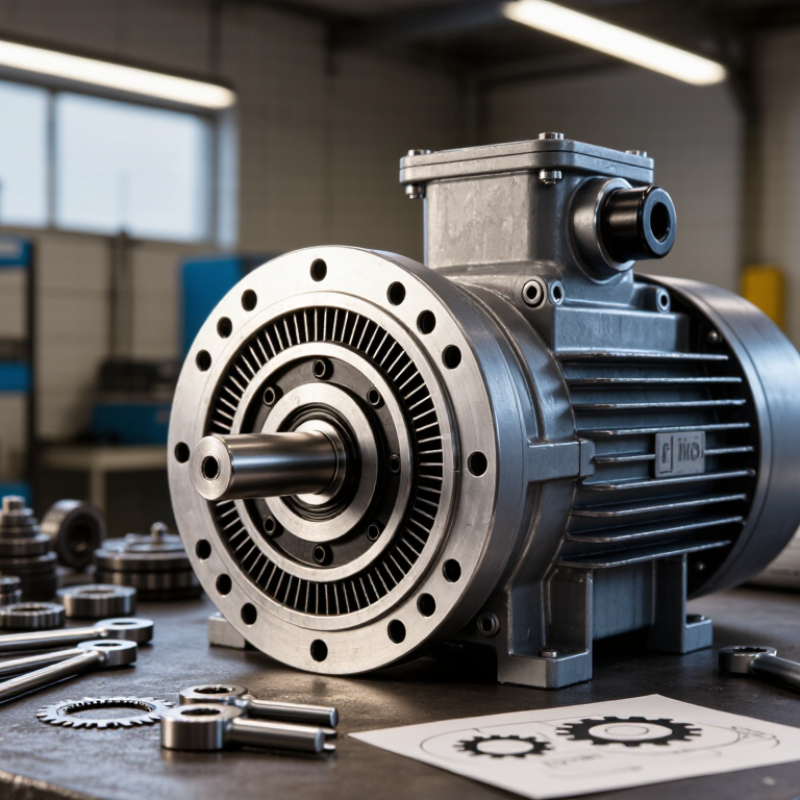
Before selecting an electric gear motor, define what the machine must do. Record required output speed, continuous torque, peak torque, acceleration time, and shaft orientation. Measure the real load, not only the catalog estimate. Startup loads can briefly exceed running torque by several times.
Duty cycle matters. A motor running for ten minutes per hour needs different thermal capacity from one operating continuously. The International Energy Agency reports that electric motor systems consume roughly 46% of global electricity. Small efficiency losses therefore deserve attention. Specify voltage, frequency, control method, braking needs, and acceptable speed variation. Keep it practical.
Inspect the working environment closely. Dust, washdown water, heat, vibration, and limited airflow can change the enclosure and cooling requirements. The U.S. Department of Energy identifies motor-driven equipment as a major share of industrial electricity use, so efficiency should be evaluated across the complete drive system. Include gearbox efficiency, transmission losses, and standby consumption.
I have seen projects fail because the estimated load looked reasonable. The conveyor was heavier in winter. A neat spreadsheet can still mislead. Define the worst credible condition, then verify it with measurements. Allow a sensible service margin, but avoid excessive oversizing; it can increase cost, reduce efficiency, and weaken low-speed performance. Record these requirements in one technical sheet before comparing suppliers.
Start with the load, not the catalog. Measure the required torque, speed, duty cycle, and starting resistance. For a conveyor moving 80 kilograms, calculate acceleration torque, friction, and incline force.
Output torque can be estimated with T = 9550P/n, where power is in kilowatts and speed is in revolutions per minute.
Add a realistic service margin, usually 20–30%, rather than doubling the motor without evidence. Torque comes first. Speed follows.
The IEA’s Energy Efficiency 2023 report estimates that electric motor systems consume about 53% of global electricity. The U.S. Department of Energy reports that motor systems use roughly 69% of industrial electricity.
These figures make efficiency more than a purchasing detail. Compare rated efficiency at the actual operating point, not only at peak performance. Check gearbox ratio, transmission losses, thermal limits, and noise.
A motor running slowly under heavy load may overheat, even when its nameplate power looks adequate. Leave room.
Select continuous or intermittent duty correctly, then verify mounting, shaft size, radial load, and braking needs.
In my own selection work, I once focused too heavily on rated torque and underestimated frequent starts. The gearbox survived, but the control system needed adjustment. That mistake still matters.
Test the motor with the real load, especially during cold starts and emergency stops. Recheck assumptions after installation, because calculated torque rarely matches a dusty factory floor perfectly.
Choosing the correct gearbox type and gear ratio determines how reliably an electric gear motor performs. Start with the driven machine, not the motor. A conveyor needing 35 revolutions per minute may use a 1,750 rpm motor. Dividing these speeds suggests a 50:1 ratio. The calculation is useful, but it is not enough.
Helical gearboxes suit continuous operation because they offer good efficiency and quiet running. Worm gearboxes provide high reduction in a compact housing, although they can produce more heat. Spur gears are simple and economical, but they may create more noise and backlash. Planetary gearboxes handle high torque in a small space, yet their cost and maintenance demands can increase. Check the load direction, duty cycle, shock level, and available installation space before selecting one type.
Do not choose a ratio only from the desired output speed. Calculate the required output torque, then include gearbox efficiency and a suitable service factor. For example, a 20 Nm motor with a 50:1 gearbox will not deliver 1,000 Nm in practice. Losses reduce the actual value. A common mistake is ignoring startup loads, especially when a conveyor begins with a full belt. Measure the real load if possible. Paper specifications can mislead. I would also check backlash, shaft alignment, lubrication, and thermal limits. A ratio that looks perfect may still overheat during long operating cycles.
10 Tips for Choosing the Right Electric Gear Motor
Evaluate Voltage, Efficiency, Duty Cycle, and Operating Conditions
Match the motor’s rated voltage with the actual supply. A mismatch can increase heat, current, and premature insulation failure. Check starting voltage too. Tip 2: confirm frequency, phase, and controller compatibility. Tip 3: calculate output torque at the gearbox shaft, not only motor torque. Tip 4: include acceleration loads, shock loads, and a realistic service factor. A spreadsheet cannot predict every stall.
Tip 5: compare efficiency at the expected load, not merely the nameplate rating. The International Energy Agency estimates motor-driven systems consume about 46% of global electricity, making small efficiency gains significant. Tip 6: review the motor’s duty cycle, such as S1 continuous or intermittent operation. Tip 7: measure the load profile across a full production shift. Many selections fail because peak demand is mistaken for average demand.
Tip 8: inspect ambient temperature, humidity, dust, vibration, and installation altitude. Tip 9: choose suitable enclosure and thermal protection. Tip 10: verify gearbox backlash, lubrication, noise, and maintenance access. IEC 60034-30-1 efficiency classes provide a useful comparison, but test conditions may differ from your application. Field technicians often find that a cooler, slightly oversized motor lasts longer, although oversizing can reduce efficiency at light loads. Recheck the calculation after installation.
| Tip | Selection Dimension | What to Evaluate | Practical Selection Guidance | Reference Example | Verification Point |
|---|---|---|---|---|---|
| 1 | Voltage and Electrical Supply | Rated voltage, available power supply, current, frequency, and allowable voltage variation. | Choose a motor whose rated voltage matches the available supply. For battery systems, confirm the controller can handle the motor's starting current. | 24 V DC system Use a motor rated for 24 V DC rather than a 12 V model. |
Check the nameplate voltage, nominal current, peak current, and power-supply tolerance. |
| 2 | Required Output Speed | Desired gearbox output speed in revolutions per minute (rpm), including speed variation during operation. | Define the target output speed before selecting the gear ratio. A higher reduction ratio generally produces lower output speed and higher output torque. | 60 rpm target A motor operating at 1,800 rpm requires an approximate 30:1 reduction ratio, before accounting for slip or controller settings. |
Confirm speed at the actual load, voltage, temperature, and control setting. |
| 3 | Output Torque | Continuous torque, peak or starting torque, acceleration torque, and load torque at the gearbox shaft. | Select a motor with sufficient continuous torque and additional margin for starting, acceleration, friction, and transient loads. Avoid sizing only from the average load. | 2.0 N·m continuous For a variable load, a practical preliminary design may target approximately 2.4–3.0 N·m rated capacity, subject to the application profile. |
Compare the gearbox's continuous and intermittent torque ratings with the real load profile. |
| 4 | Gear Ratio and Mechanical Transmission | Reduction ratio, gearbox efficiency, backlash, shaft arrangement, and allowable radial or axial load. | Use a higher ratio when low speed and high torque are required. Consider planetary, helical, spur, or worm gearing according to efficiency, compactness, noise, and self-locking needs. | 20:1 ratio A 1,500 rpm motor may provide approximately 75 rpm at the gearbox output, excluding load-dependent speed effects. |
Verify ratio accuracy, backlash, shaft loading, lubrication requirements, and mounting orientation. |
| 5 | Efficiency and Energy Consumption | Motor efficiency, gearbox efficiency, controller losses, no-load consumption, and heat generated during operation. | Evaluate total system efficiency rather than motor efficiency alone. Higher efficiency can reduce battery size, operating cost, and thermal stress. | 70% total efficiency If mechanical output is 70 W, electrical input may be about 100 W under the stated operating condition. |
Use efficiency data at the actual speed and torque, because efficiency changes with load and operating point. |
| 6 | Duty Cycle and Operating Time | Continuous or intermittent duty, on/off frequency, run time per cycle, rest time, and daily operating hours. | Choose a continuous-duty motor for uninterrupted operation. For intermittent applications, calculate the equivalent thermal load instead of relying only on the peak rating. | S3: 25% duty cycle Operating for 15 seconds followed by 45 seconds at rest gives a 25% cycle, provided the thermal limits are respected. |
Confirm the manufacturer's duty classification, allowable starts per hour, and thermal time constant. |
| 7 | Starting, Acceleration, and Braking | Starting torque, acceleration time, inertia of the driven load, braking method, and reversal frequency. | Allow extra torque for acceleration of high-inertia loads. Frequent starts, stops, reversals, or rapid braking may require a larger motor, current-limited drive, or dedicated brake. | High-inertia conveyor Use controlled acceleration and verify that peak current and gearbox shock loads remain within limits. |
Calculate reflected inertia and check peak torque, peak current, stopping time, and mechanical shock. |
| 8 | Environmental Conditions | Ambient temperature, humidity, dust, water exposure, corrosive agents, altitude, vibration, and installation location. | Select suitable enclosure protection and materials. Outdoor, washdown, dusty, or chemically exposed equipment needs stronger environmental protection than indoor equipment. | IP65 requirement An IP65 enclosure is dust-tight and protected against water jets, but it is not intended for immersion. |
Confirm IP rating, insulation class, permissible ambient temperature, corrosion resistance, and altitude derating. |
| 9 | Size, Mounting, and Noise | Available installation space, mounting pattern, shaft dimensions, cable direction, operating noise, and vibration. | Compare the motor and gearbox envelope with the available space. A compact design should still provide adequate cooling and safe access for installation and maintenance. | Limited enclosure space Prioritize the required torque and thermal performance before minimizing overall dimensions. |
Check mounting holes, shaft fit, cable clearance, noise level, vibration limits, and service access. |
| 10 | Control, Protection, and Service Life | Controller compatibility, overload protection, stall protection, feedback, expected service life, lubrication, and maintenance access. | Use current limiting, thermal protection, and suitable feedback when speed or position must be controlled accurately. Select a service-life rating appropriate for the required operating hours. | Closed-loop speed control An encoder can provide speed feedback and help detect stalls or excessive load conditions. |
Verify controller ratings, thermal sensors, encoder compatibility, replacement parts, lubrication intervals, and expected L10 bearing life where applicable. |
Note: Values shown are general engineering reference examples. Final selection should be based on the complete load profile, measured operating conditions, applicable safety requirements, and the motor-drive system's technical data.
Choosing the right electric gear motor starts with the mounting arrangement. In field installations, a motor that fits the drawing may still clash with guards, shafts, or cable routes. Check flange dimensions, shaft height, bolt access, and available service space before ordering. A few millimeters can create hours of rework. I once underestimated connector clearance, and the replacement bracket delayed testing.
Control features deserve equal attention. Match the motor with the required speed range, starting method, braking response, and load profile. Some applications need an encoder for accurate positioning, while others only need simple variable-speed control. Confirm voltage, current, feedback signals, and protection settings together. A control panel can appear compatible but behave poorly during sudden load changes. Test the motor under realistic conditions, not only without a load.
Durability depends on more than a sealed housing. Examine gear materials, bearing quality, thermal limits, duty cycle, and resistance to dust or moisture. Listen for rising noise and feel for unusual vibration during routine checks. Maintenance access matters too. Grease points, inspection covers, replaceable seals, and clear service instructions reduce downtime. Still, maintenance plans are often too optimistic. Actual dust, heat, and frequent starts may shorten service intervals. Record temperature, vibration, and running hours, then adjust the schedule when evidence disagrees with the original estimate.
Record output speed, continuous torque, peak torque, acceleration time, and shaft orientation. Measure the actual machine load.
Startup loads can exceed running torque several times. A fully loaded conveyor may require much more torque at launch.
A motor running ten minutes per hour needs less thermal capacity than one operating continuously. Check heating carefully.
Inspect dust, water, heat, vibration, and airflow. These conditions influence enclosure design and cooling requirements.
No. Evaluate motor efficiency, gearbox losses, transmission losses, and standby consumption across the complete drive system.
Divide motor speed by required output speed. For example, 1,750 rpm divided by 35 rpm suggests a 50:1 ratio.
No. Verify output torque, gearbox efficiency, service factor, startup load, and thermal limits. A neat calculation can still mislead.
Helical gearboxes support quiet, continuous operation. Worm types offer compact reduction but may produce more heat.
Ignoring startup loads, backlash, shaft alignment, lubrication, and heat buildup can cause failure. Oversizing also wastes money.
Loads may change with season, material, or belt filling. Measure difficult conditions, then keep a sensible service margin.
Choosing the right Electric Gear Motor begins with a clear understanding of the application. Identify the required load, movement pattern, operating environment, and available space before comparing models. The motor should provide sufficient torque, speed, and power for both normal operation and occasional peak demands without unnecessary energy consumption. Selecting the correct gearbox type and gear ratio is equally important, as these factors influence output speed, torque multiplication, noise, and overall performance.
Next, evaluate the electrical voltage, efficiency, duty cycle, temperature, moisture, dust, and vibration conditions of the installation site. Consider practical features such as mounting options, speed control, braking, feedback, and protection functions. A durable design can reduce failures, while accessible components and simple maintenance can lower long-term operating costs. By balancing performance requirements, environmental conditions, control needs, installation constraints, and maintenance expectations, you can choose an Electric Gear Motor that delivers reliable, efficient, and consistent service.
