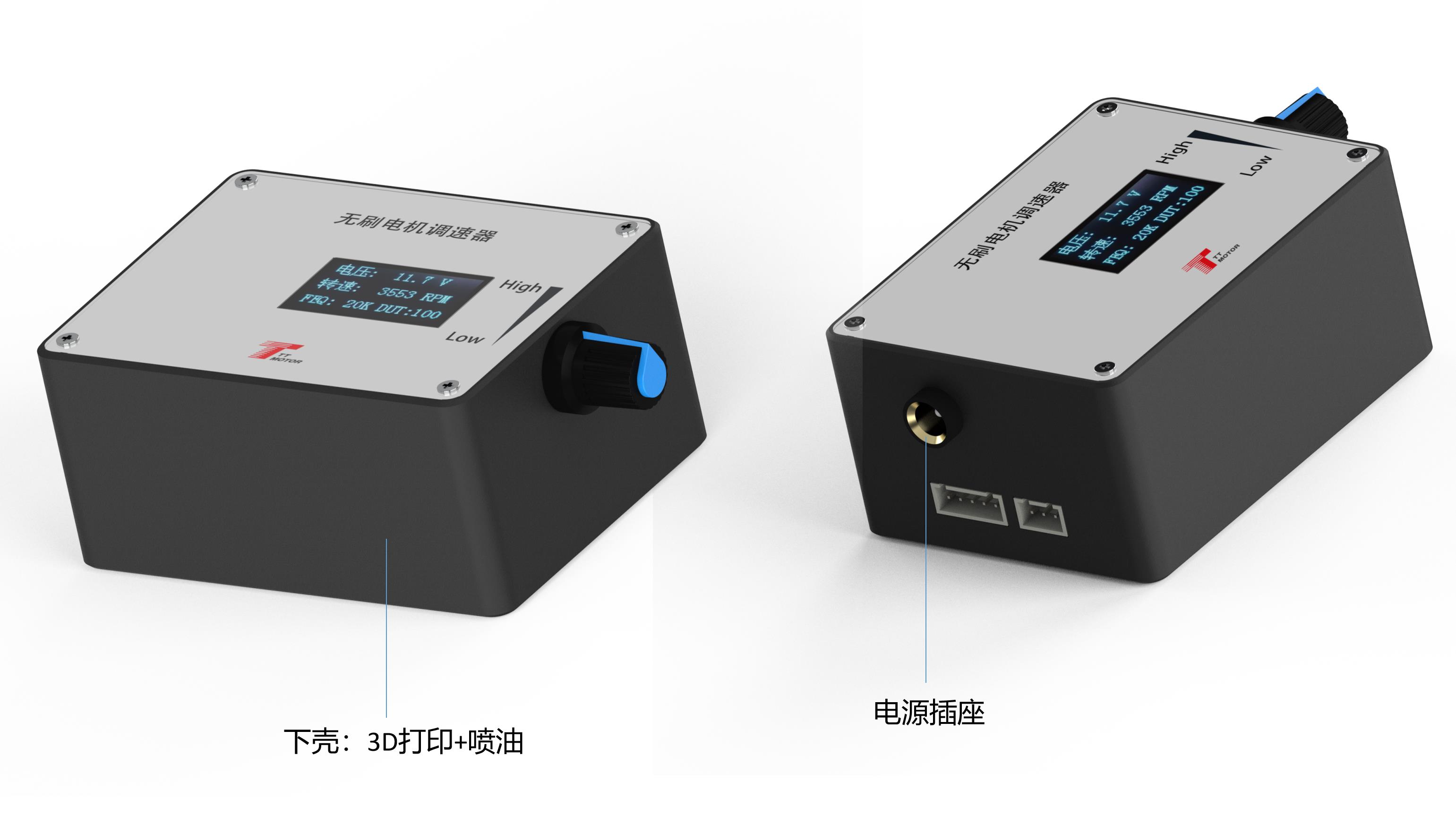
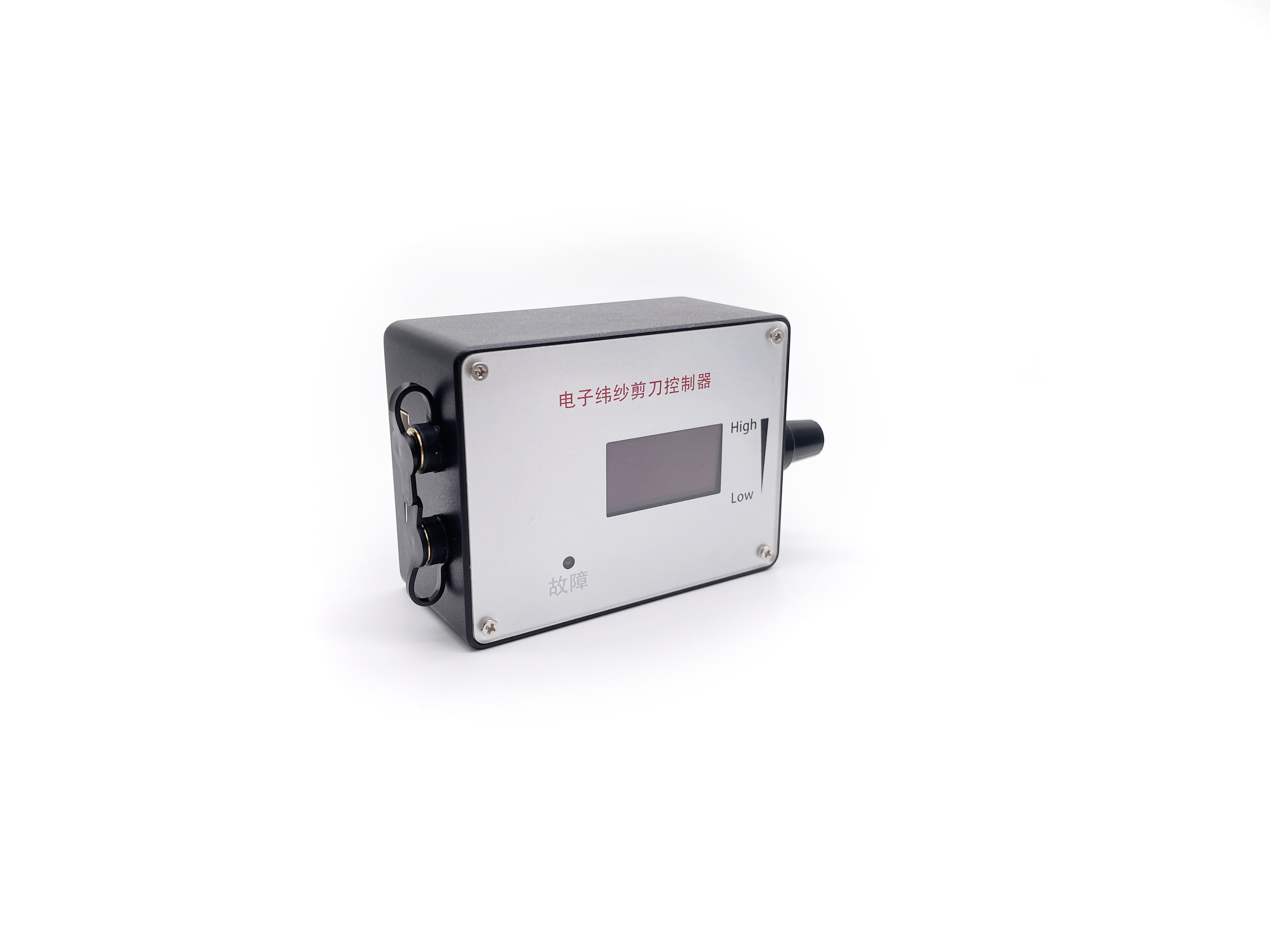
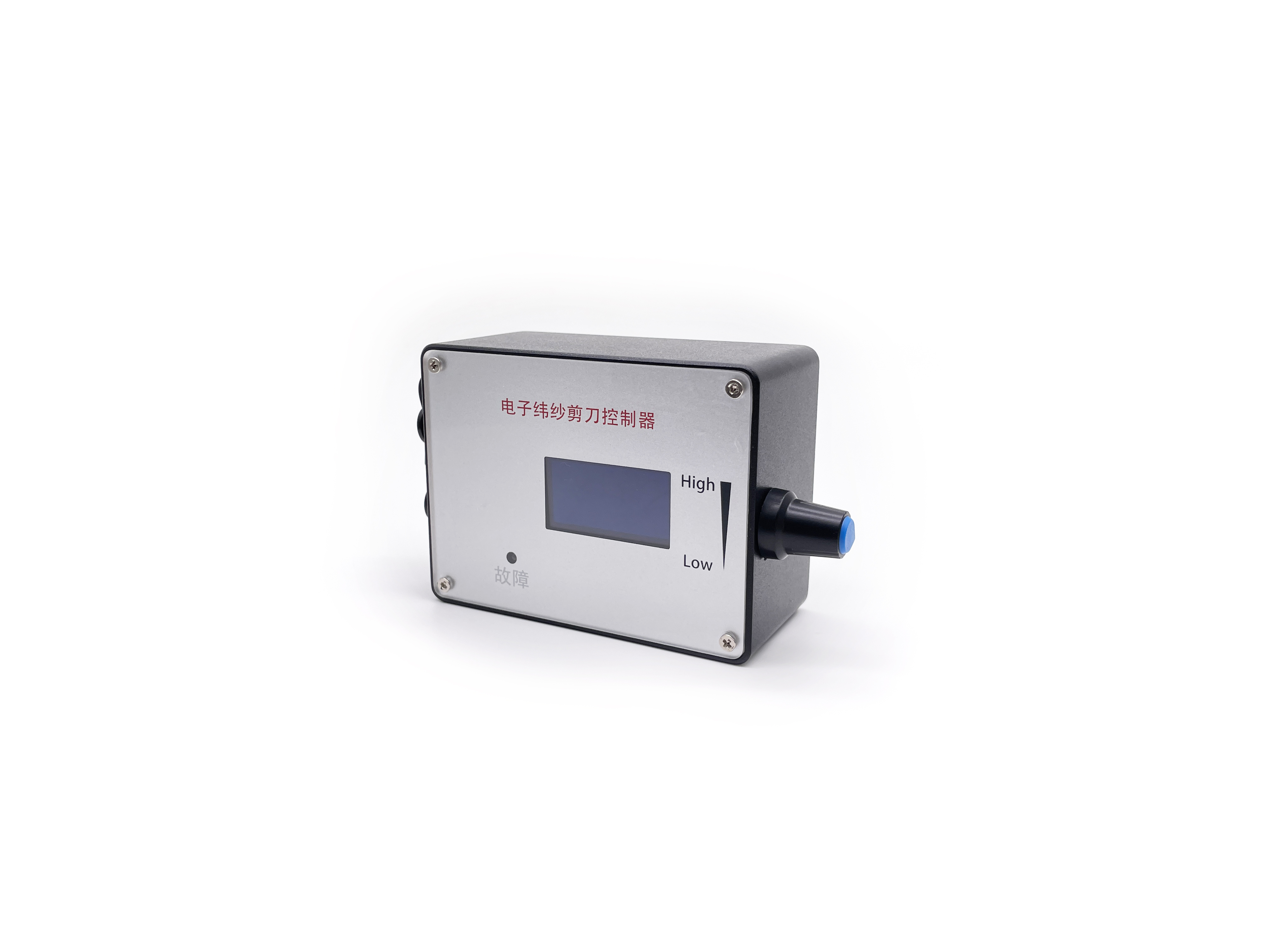
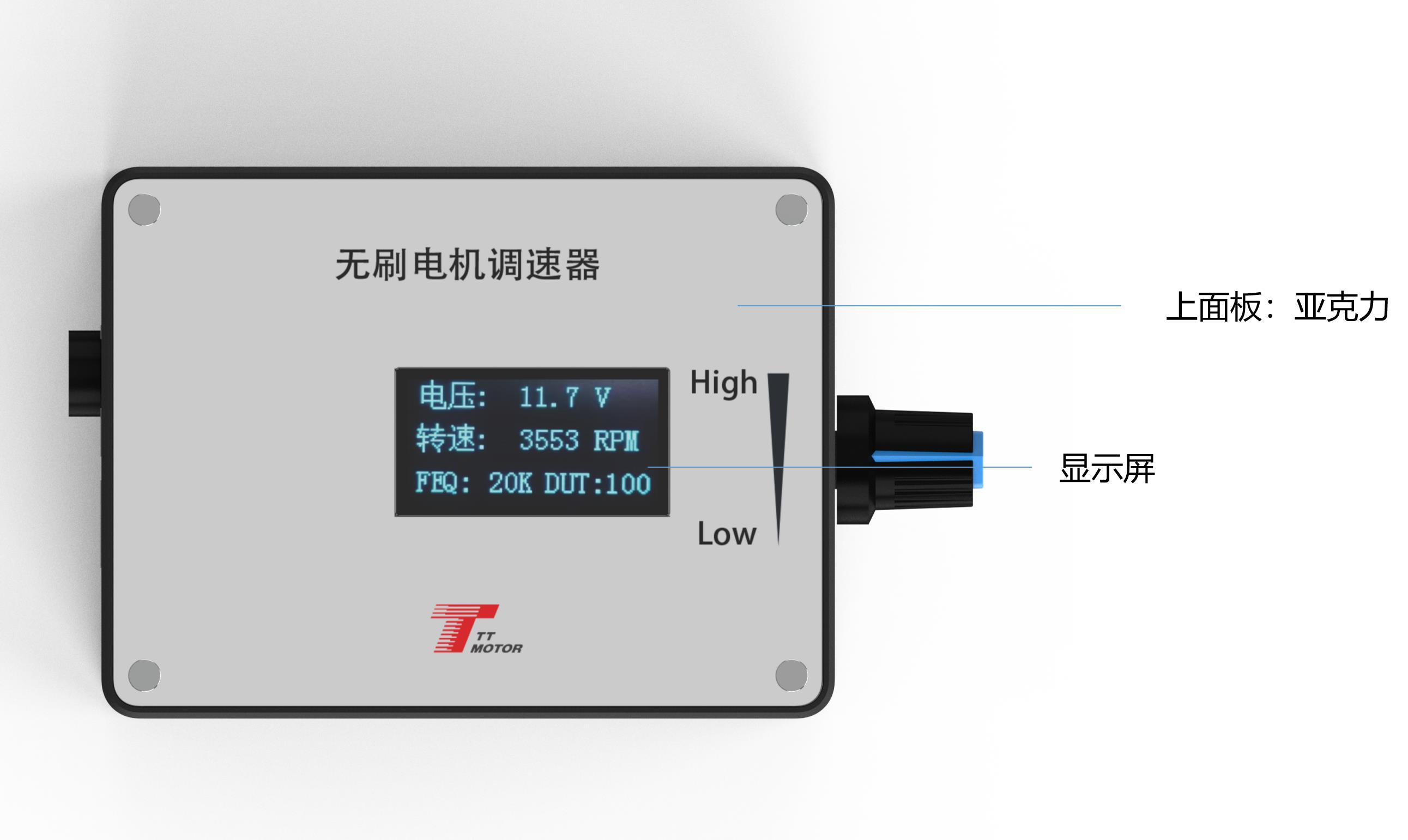
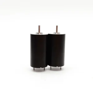
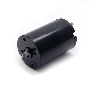
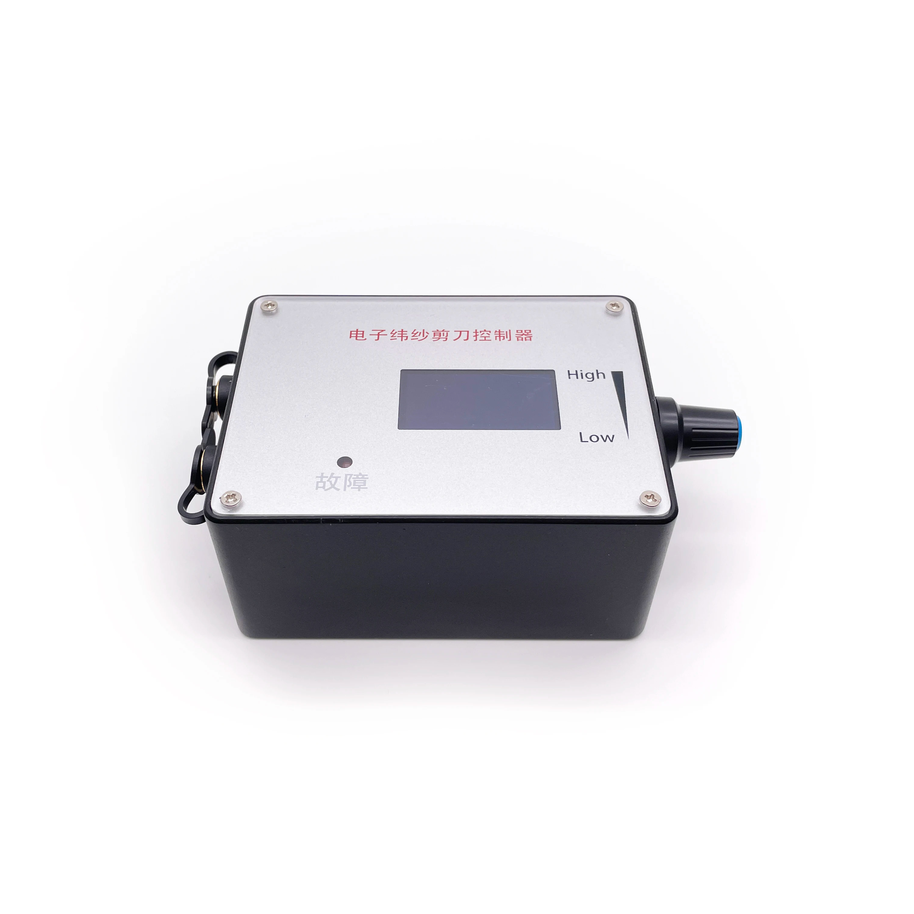
Motor Speed Controller, DC 5V-36V 3-Phase Brushless Motor Speed Control CW CCW Reversible Switch

Product Description

1. Electrical Performance Specifications
Governor Specifications
  • Voltage Range: DC 5V - 28V.
  • Rated Current: MAX 2A. (For higher current, connect motor power line directly to supply).
  • PWM Output Frequency: 0 ~ 100KHz.
  • Analog Voltage Output: 0 - 5V.
  • Temperature Range: Working: -10℃ to 70℃; Storage: -30℃ to 125℃.
  • Driver Board Size: 60mm (L) x 40mm (W).
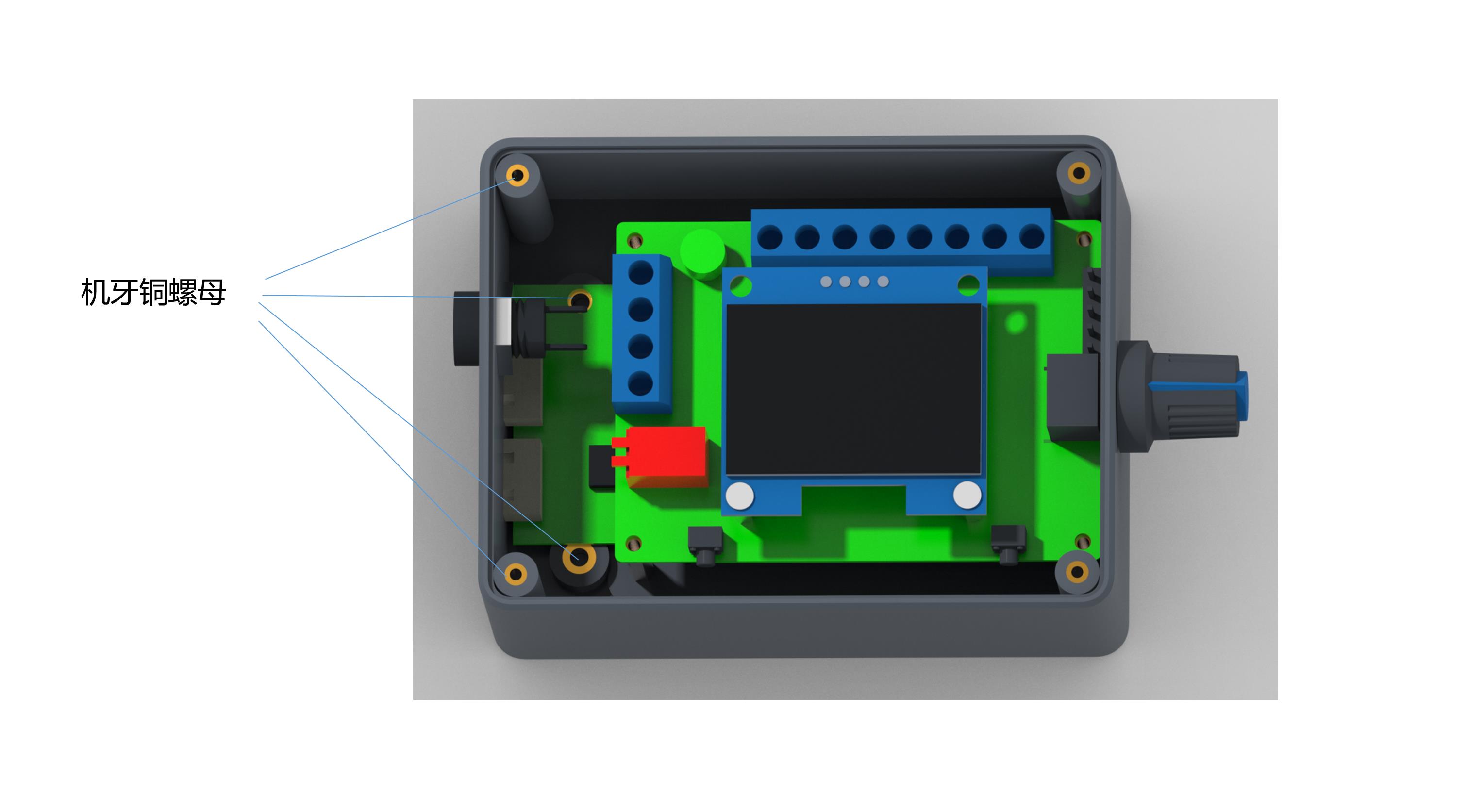
🔌 2. Wiring and Internal Function Description
  • ① Positive power supply input for governor/motor.
  • ② Negative power supply input for governor/motor.
  • ③ Positive output of the power supply to the motor.
  • ④ Negative output of the power supply to the motor.
  • ⑤ Rotation Control (F/R): High (5V) and Low (0V) level output for direction control. Default is High.
  • ⑥ Brake Control (BRA): High (5V) and Low (0V) level output. Power-on default is High.
  • ⑦ Analog Voltage Output (0-5V): Suitable for motors accepting analog voltage speed regulation.
  • ⑧ PWM1 Reverse Output: Speed is inversely proportional to duty cycle.
  • ⑨ PWM2 Forward Output: Speed is proportional to duty cycle.
  • ⑩ Feedback Signal Input: Accepts motor feedback signal. Adjust sensitivity via jumper caps (FG for single, FG*3 for triple feedback).
⚙️ 3. Governor Parameter Settings
Frequency Setting: Press and hold Switch 1 before power-on. Once "FEQ:20K" appears, release the button. Use Switch 1 to reduce and Switch 2 to increase. Factory default is 20KHz.
Number of Poles: Hold Switch 1 and Switch 2 simultaneously before power-on. Release when "number of poles: 1 polarity" appears. Adjust as needed for the specific motor.
Feedback & Direction:
  • FG/FG*3 Pin: Add jumper cap for 3x feedback; remove for single feedback.
  • CW/CCW Pin: Set initial state direction. Add jumper cap for CCW; remove for CW.
⚠️ 4. Important Precautions
  • Connection: The positive and negative power supply must be connected correctly. Reversing polarity will damage and burn the governor.
  • Compatibility: The governor is designed to match motors with compatible control interfaces.
  • Voltage Limit: The control ports (⑤ to ⑨) must not exceed 5V voltage input.
Frequently Asked Questions
Q: What is the input voltage range for this governor?
A: The governor supports a DC voltage range from 5V to 28V.
Q: Can I use this governor for a motor that requires more than 2A?
A: Yes, but the motor power line must be connected directly to the power supply, not through the governor's internal circuit.
Q: How do I change the PWM frequency?
A: Hold Switch 1 during power-on until the frequency screen appears, then adjust using the switches. The default is 20KHz.
Q: What happens if I reverse the positive and negative power wires?
A: Reversing the power supply will cause the governor to fail and will likely burn the internal components.
Q: Does the unit support motor speed feedback?
A: Yes, it features an FG feedback input that can be configured for single or triple feedback multiples via jumper caps.
Q: How can I set the initial rotation direction?
A: You can use the CW/CCW pin settings. Adding a jumper cap sets it to CCW, while removing it sets it to CW.
Related Products