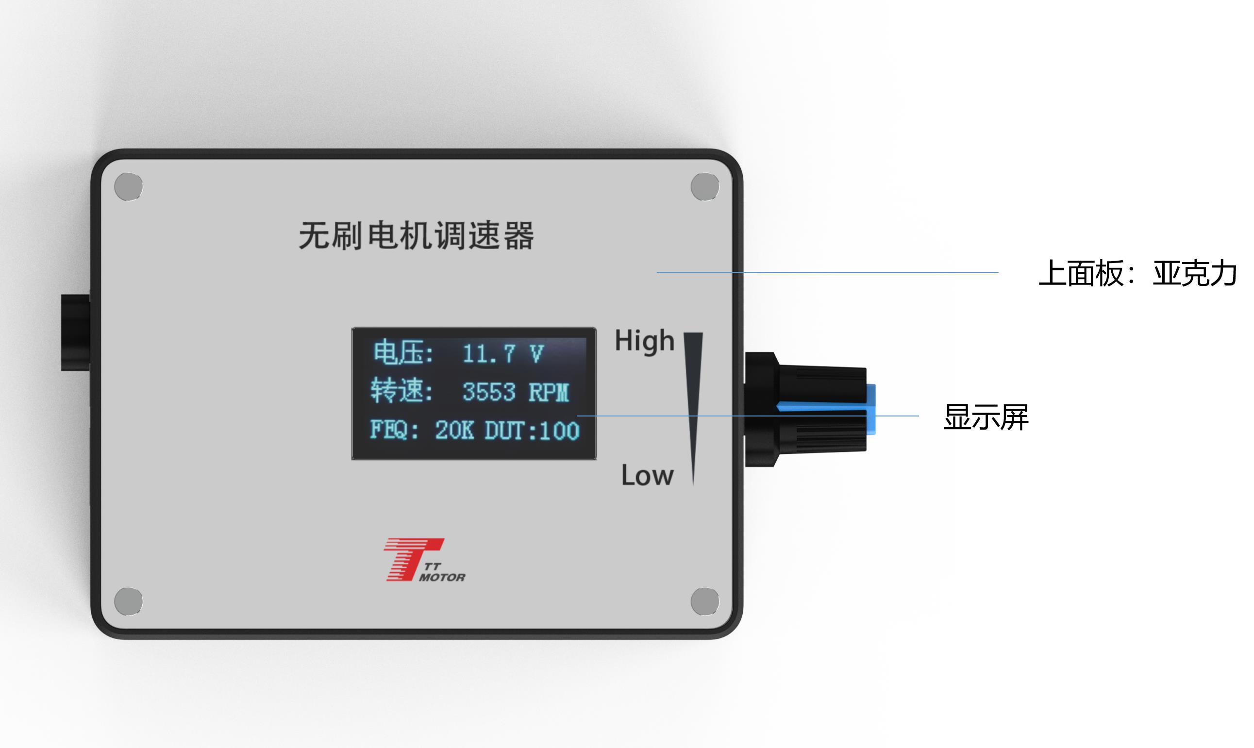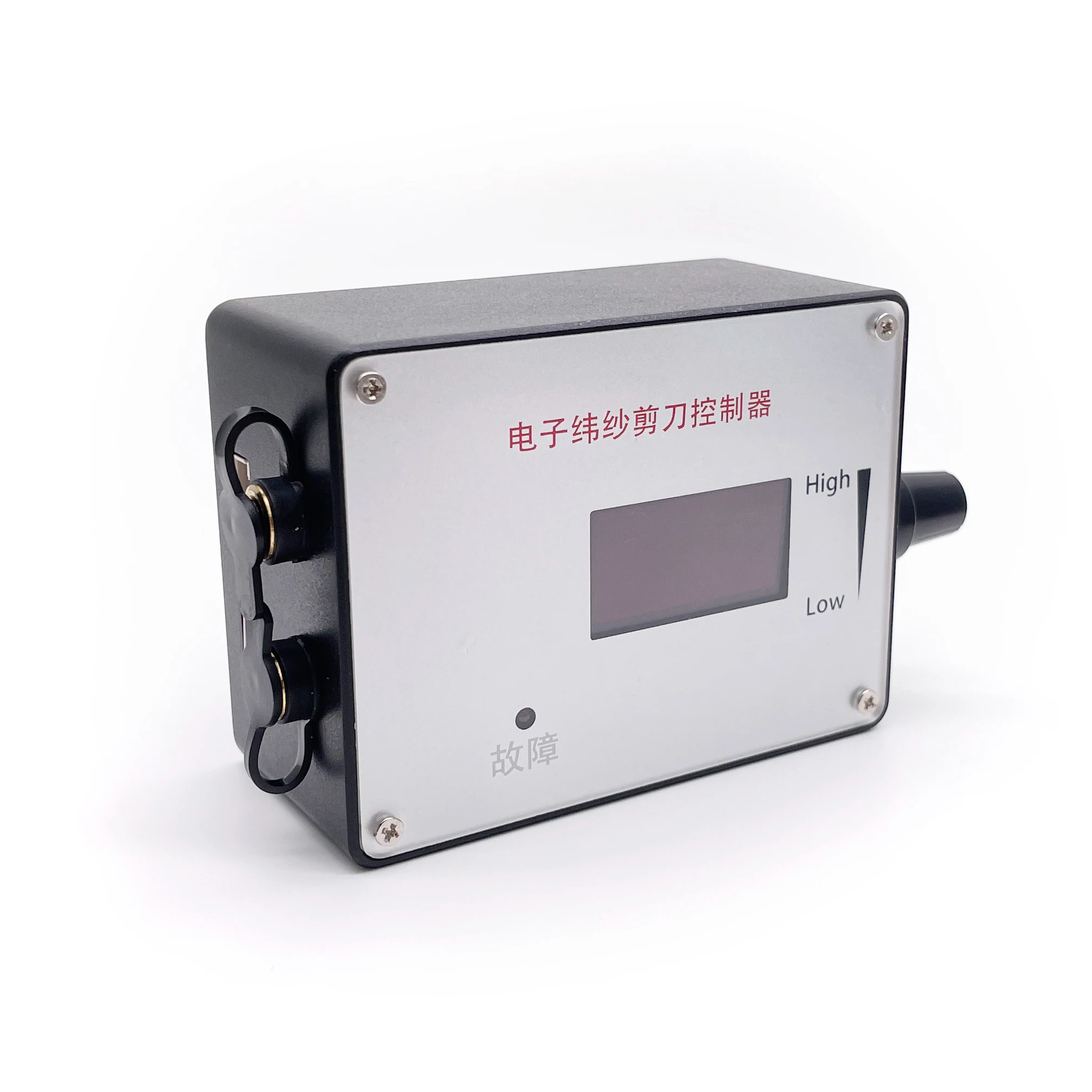
DC Motor Speed Controller DC 12V 24V DC Brushless Motor Speed Controller With Forward-Brake-Reverse Switch Ajustable Display

Product Description

Governor Specifications

1. Electrical Performance Specifications

Voltage Range: DC5V-28V
Rated Current: MAX 2A (Note: High current motors should bypass the governor for power)
PWM Frequency: 0 ~ 100KHz
Analog Output: 0-5V
Working Temp: -10℃ to 70℃
Storage Temp: -30℃ to 125℃
Size: 60mm (L) X 40mm (W)

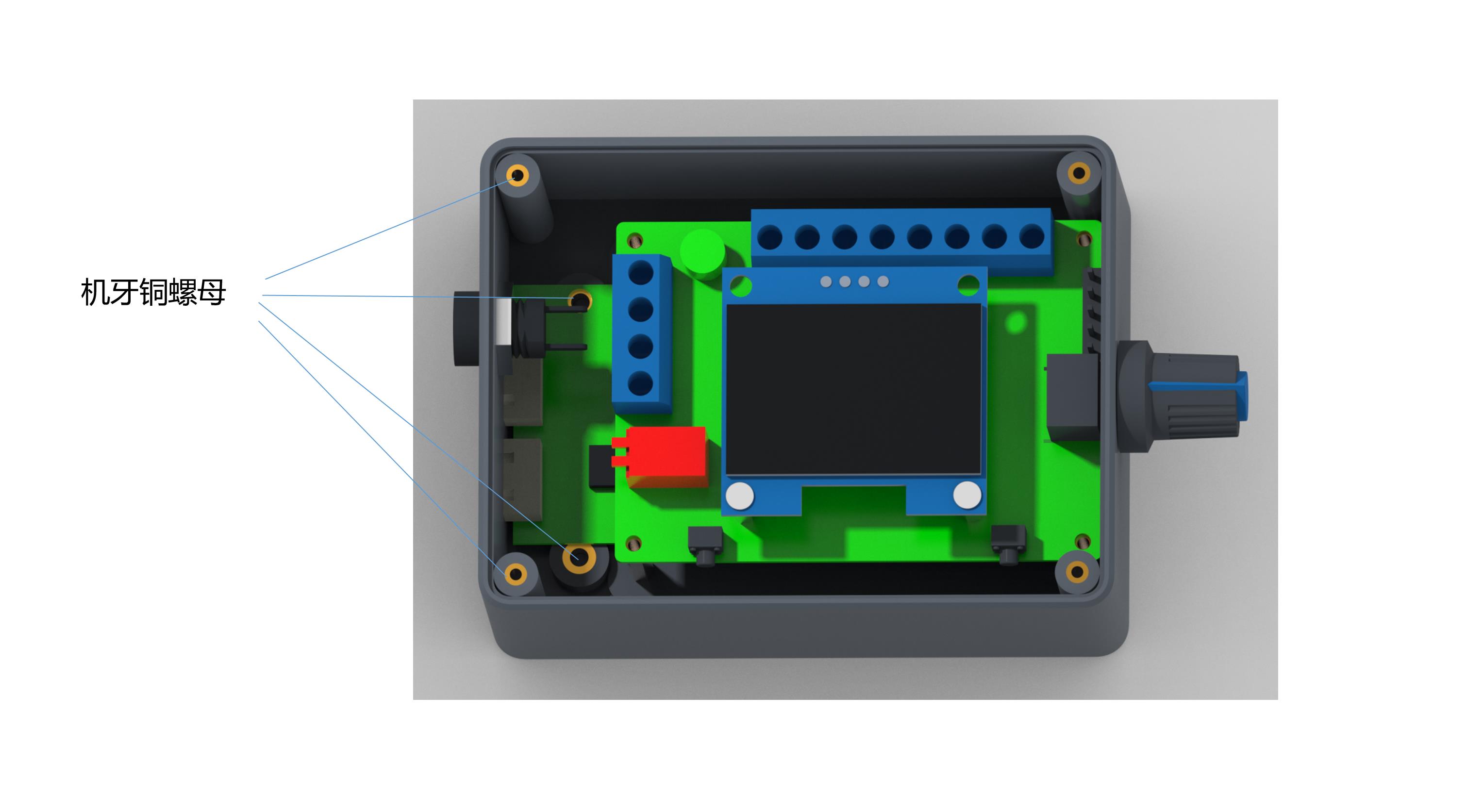
2. Governor Wiring and Internal Functions

  • 1 Governor & Motor Power Positive (+) Input
  • 2 Governor & Motor Power Negative (-) Input
  • 3 Motor Power Positive (+) Output
  • 4 Motor Power Negative (-) Output
  • 5 F/R Control: High (5V) / Low (0V) levels for rotation control. Default: High.
  • 6 Brake Control (BRA): High (5V) / Low (0V) levels. Default: High.
  • 7 Analog Voltage Output: 0~5V for speed regulation.
  • 8 PWM1 Reverse Output: Speed is inversely proportional to duty cycle.
  • 9 PWM2 Forward Output: Speed is proportional to duty cycle.
  • 10 FG/FG*3: Motor feedback signal input (Jumper selectable).

3. Parameter Settings

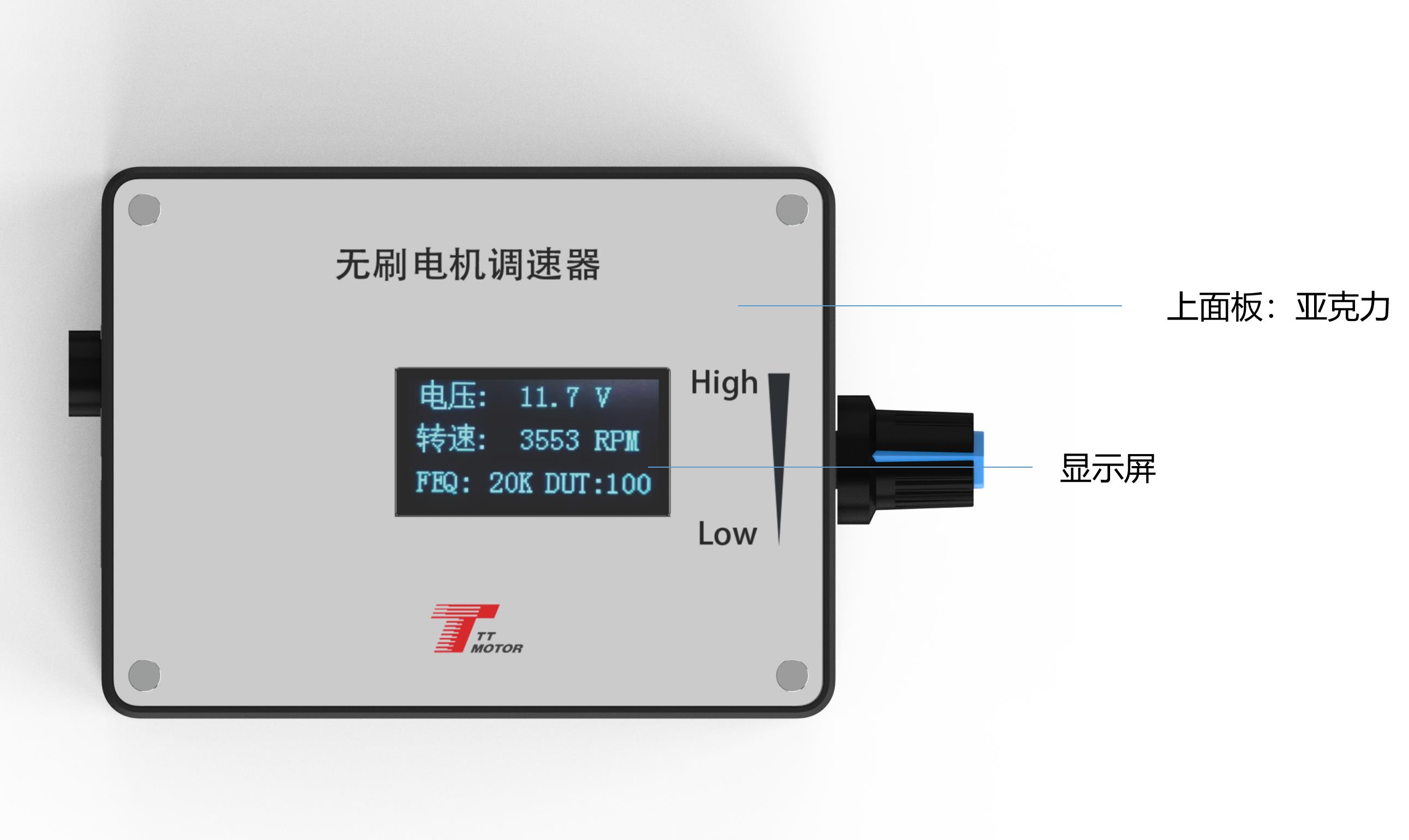
Frequency Setting: Hold Switch 1 before power-on. Once "FEQ:20K" displays, use Switch 1 to reduce and Switch 2 to increase. (Default: 20KHz).

Pole Number Setting: Hold both Switch 1 and 2 before power-on. Adjust poles using Switch 1/2 when display shows "Pole Number". (Default: 1 Pole).

Feedback (FG) Setting: Use Jumper cap on FG/FG*3 pins. No cap = Single FG; With cap = 3x FG.

Direction (CW/CCW) Setting: Use Jumper cap on CW/CCW pin. No cap = CW; With cap = CCW.

4. Important Precautions

1. Polarity Protection: Ensure positive and negative power inputs are correctly connected. Reversing polarity will burn the governor.

2. Compatibility: Designed for motors matching the specified control interfaces.

3. Voltage Limit: Do not exceed 5V on the five control ports (Wiring pins 5 through 9).
Frequently Asked Questions

Q1: What is the maximum current this governor can handle?
The rated current is MAX 2A. For motors requiring higher current, the power line should be connected directly to the power supply, bypassing the governor.
Q2: Can I use this with a 24V DC power source?
Yes, the governor supports a voltage range from DC 5V up to 28V.
Q3: How do I change the default frequency of 20KHz?
Before powering on, hold down touch switch 1. After power-on, wait for the screen to show the frequency, then use switch 1 and 2 to adjust.
Q4: What happens if I reverse the positive and negative wires?
Reversing the power supply connections will cause the governor to fail and likely burn out the internal components.
Q5: How does the FG feedback setting work?
It is controlled via a jumper cap. Without the cap, it is set to single FG; adding the jumper cap changes it to 3 times FG (FG*3).
Q6: What does the main screen display?
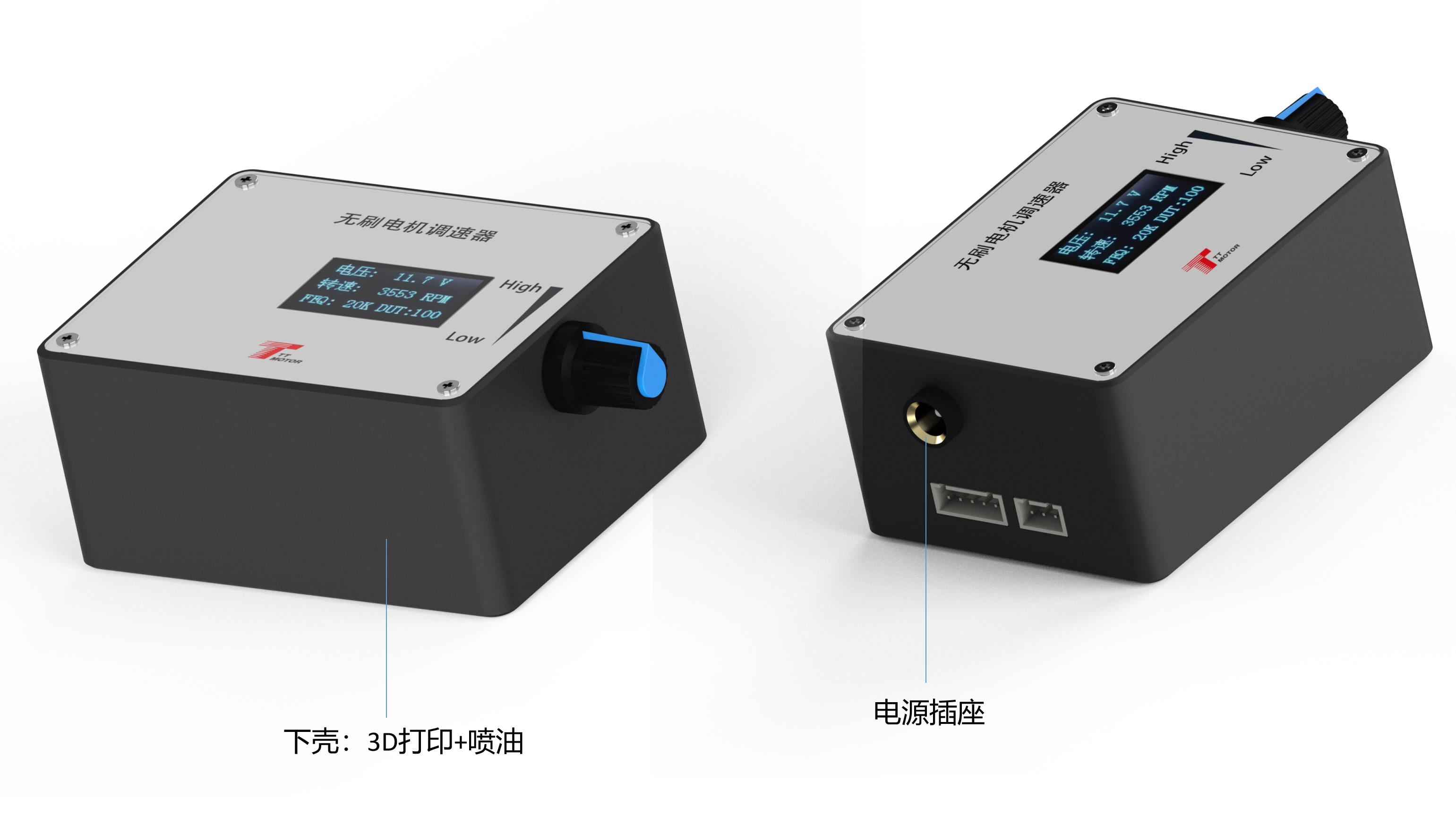
The main screen monitors four key parameters: input voltage, speed, frequency, and duty cycle.

Related Products